Isolation and Drive Circuit and Output Power Switch
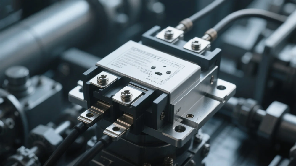
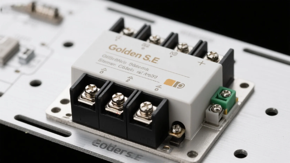
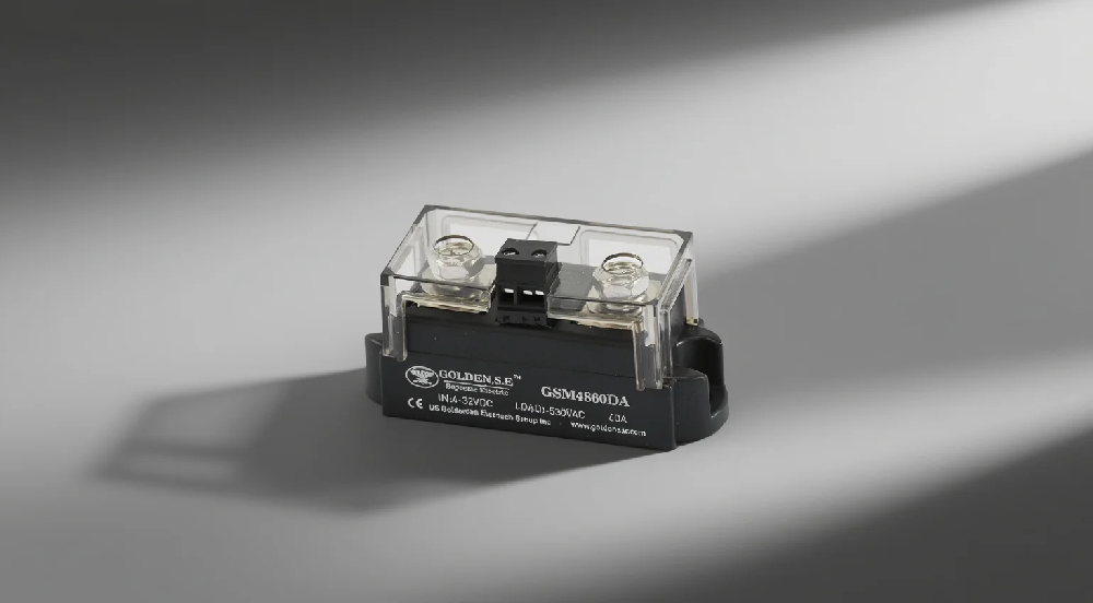
Solid-state relays are contactless electronic switches that use semiconductor devices (such as thyristors and transistors) to control circuit on-off states and achieve electrical isolation between input and output through optocouplers or transformers. The internal structure of a solid-state relay can be divided into three major modules: input control circuit, isolation and drive circuit, and output power switch. Today, we will focus on the electronic components used in the isolation and drive circuit and output power switch.
Thyristor
1. Definition of Thyristor
A thyristor (Silicon Controlled Rectifier, SCR) is a three-terminal semiconductor power device with a PNPN four-layer structure. In solid-state relays, it is mainly used as a control switch for AC loads, featuring unidirectional conductivity and controllable conduction. Unlike transistors, once a thyristor is turned on, it remains in the on state even if the trigger signal is removed.
2. Working Principle of Thyristor
2.1 Basic Structural Characteristics
- Composed of three terminals: anode (A), cathode (K), and gate (G);
- Has an alternating structure of three PN junctions;
2.2 Triggering and Conduction Mechanism
- Conducts when a sufficient trigger current (typically 5-50mA) is applied to the gate;
- Remains on until the anode current drops below the holding current;
2.3 AC Control Characteristics
- Voltage control of AC power is achieved by controlling the trigger phase;
- Automatically turns off at the natural zero crossing point;
3. Role of Thyristor in SSR
3.1 Core Switch Function
- Realizes contactless on-off control of AC loads;
- Can typically carry currents of several hundred amperes;
3.2 Photoelectric Isolation Drive
- Combined with optocouplers to achieve isolation of the control loop;
- Isolation voltage typically reaches 2.5-5kV;
3.3 Special Application Advantages
- Zero-voltage turn-on reduces electromagnetic interference;
- No mechanical wear with a lifespan of over 10^8 operations;
3.4 Protection Characteristics:
- Built-in dv/dt protection to prevent false triggering;
- Can withstand high surge currents when combined with a heat sink;
Thyristor-based SSRs are particularly suitable for controlling high-power loads such as AC motors and heaters. Modern intelligent SSRs also integrate zero-crossing detection functions to effectively suppress current surges during turn-on.

Insulated Gate Bipolar Transistor (IGBT)
1. Definition of IGBT
An IGBT (Insulated Gate Bipolar Transistor) is a composite fully controllable voltage-driven power semiconductor device that combines the high input impedance of MOSFETs and the low on-resistance of BJTs to achieve efficient power control. In solid-state relays, it serves as the core switching element with a three-terminal structure (collector, emitter, and gate), where the gate is electrically isolated by a silicon dioxide insulating layer.
2. Working Principle of IGBT
2.1 Composite Structural Characteristics
- The input side adopts the MOSFET gate control structure;
- The output side inherits the bipolar conduction characteristics of BJTs;
- Forms a PNPN four-layer semiconductor structure;
2.2 Conduction Mechanism
- A forward voltage applied to the gate forms a conductive channel;
- Electron injection into the N-drift region triggers a hole injection effect;
- Generates bipolar carrier conduction to reduce on-resistance;
2.3 Turn-off Characteristics
- After the gate voltage is removed, there is a minority carrier storage effect;
- Turn-off time is affected by the carrier recombination rate;
3. Role of IGBT in SSR
3.1 High-performance Switch Function
- Supports kHz-level high-frequency switching operations;
- On-resistance is reduced to 1.5-3V (50% lower than MOSFETs);
- Withstands voltages up to 1200-6500V;
3.2 Drive Isolation Design Ø Gate drive power < 1W (only 1/10 of BJT);
Ø Can be used in conjunction with optocoupler / transformer isolation drive;
3.3 Special application advantages
Ø Built-in freewheeling diode for handling inductive loads;
Ø Supports PWM precise control;
Ø Operating junction temperature up to 150℃;
3.4 System protection features
Ø Integrated temperature sensing function;
Ø Short-circuit withstand time up to 10μs level;
IGBT type SSR is particularly suitable for applications requiring high-frequency switching such as inverters and UPS. Modern intelligent SSR adopts IGBT modular design, with multiple chips connected in parallel to achieve hundreds of amperes current carrying capacity. Its composite structure characteristics enable SSR to have both fast response and low conduction loss advantages.
RC Absorption Circuit

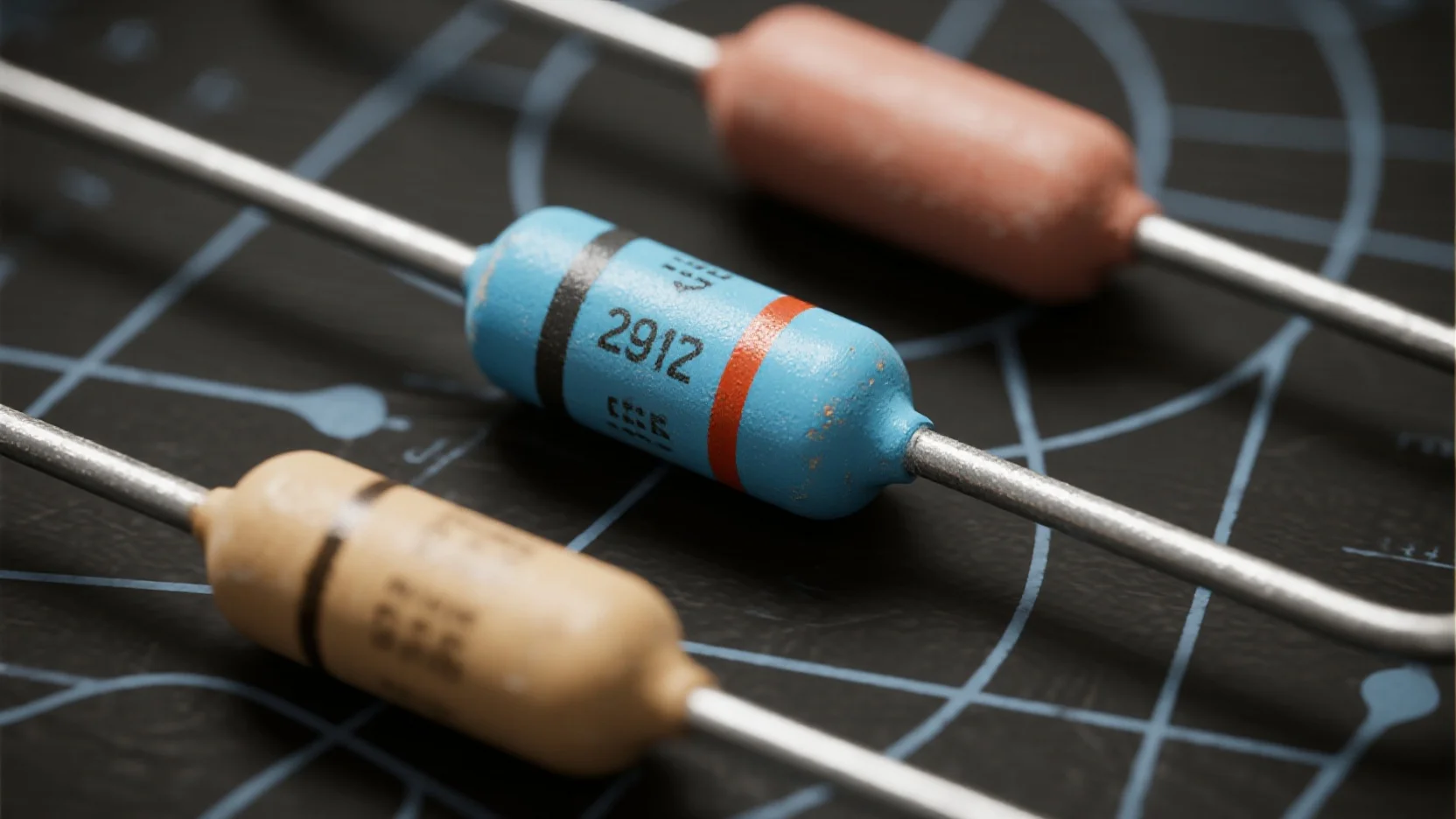
The RC absorption circuit in solid-state relays (SSR) is an important protection circuit mainly used to suppress voltage surges and electromagnetic interference during the switching process. It consists of a resistor (R) and a capacitor (C) connected in series and is connected in parallel to the output terminals or the switching devices of the SSR. It is a passive buffer circuit that protects semiconductor devices from voltage spikes by absorbing transient energy.
1. Working principle
Ø When the switch is turned off: The energy stored in the parasitic inductance charges the parasitic capacitance, and at the same time charges the absorption capacitor through the absorption resistor. The absorption resistor increases the equivalent impedance, which is equivalent to increasing the parallel capacitance of the switch, thereby suppressing voltage surges.
Ø When the switch is turned on: The absorption capacitor discharges through the switch, and the discharge current is limited by the absorption resistor to avoid excessive current impact.
Ø Zero-crossing control coordination: In AC SSR, the RC circuit works in coordination with the zero-crossing control circuit to complete the on-off operation at the zero-crossing point of the voltage, further reducing harmonic interference.
2. Core functions
Ø Suppressing voltage rise rate (dv/dt): By taking advantage of the characteristic that the voltage across the capacitor cannot change abruptly, it limits the voltage change rate across the switching devices, preventing false triggering or breakdown.
Ø Damping oscillation: The series resistor can consume the oscillation energy in the RLC circuit, preventing overvoltage damage to devices such as thyristors due to resonance.
Ø Absorbing surge energy: When there is an inductive load (such as transformer leakage inductance) in the circuit, it absorbs the surge voltage and current spikes.
Ø Reducing radio frequency interference: Reduces the high-frequency noise generated during the switching process and its electromagnetic interference to the power grid and other equipment.
3. Typical application scenarios
Ø Protecting switching devices such as bidirectional thyristors from power spikes.
Ø Used in conjunction with zero-crossing control circuits in AC SSR.
Ø Switch protection for high inductive loads (such as motors, relay coils).
The RC absorption circuit is a key design for ensuring the reliable operation of SSR and its parameters need to be adjusted according to the specific load characteristics.
Varistor

A varistor is a nonlinear resistor device whose resistance value changes significantly with the applied voltage. In SSR, zinc oxide (ZnO) varistors are typically used and connected in parallel to the output terminals or the switching devices as the core component for overvoltage protection.
1. Working principle
Ø Voltage clamping characteristic: It presents a high resistance state (megohm level) when the voltage across it is below the threshold, and rapidly turns into a low resistance state (ohm level) when the voltage exceeds the rated value (e.g., 470V varistor for AC380V SSR), forming a discharge path.
Ø Energy absorption mechanism: Utilizing the nonlinear volt-ampere characteristic of semiconductor materials, it converts surge energy into heat energy for dissipation, with a response time of nanosecond level.
Ø Self-recovery characteristic: Automatically returns to a high resistance state after the overvoltage disappears, without the need for manual intervention.
2. Core role in SSR
3. Typical application scenarios Ø Communicative SSR: When used in conjunction with RC absorption circuits, it forms a dual protection system (varistors mainly deal with high-voltage surges, while RC circuits suppress high-frequency oscillations).
Ø Inductive load control: Particularly suitable for loads such as motors and transformers that are prone to generating counter electromotive force.
Ø Harsh grid environment: Protection for equipment in areas with significant grid fluctuations or frequent lightning strikes.
In SSRs, varistors and RC absorption circuits often form a complementary protection system: the former deals with high-voltage and high-energy surges, while the latter handles high-frequency and low-energy oscillations. In practical applications, parameter matching should be carried out based on load characteristics (such as the current multiple during motor start-up and stop).


