Isolation and Drive Circuit and Output Power Switch
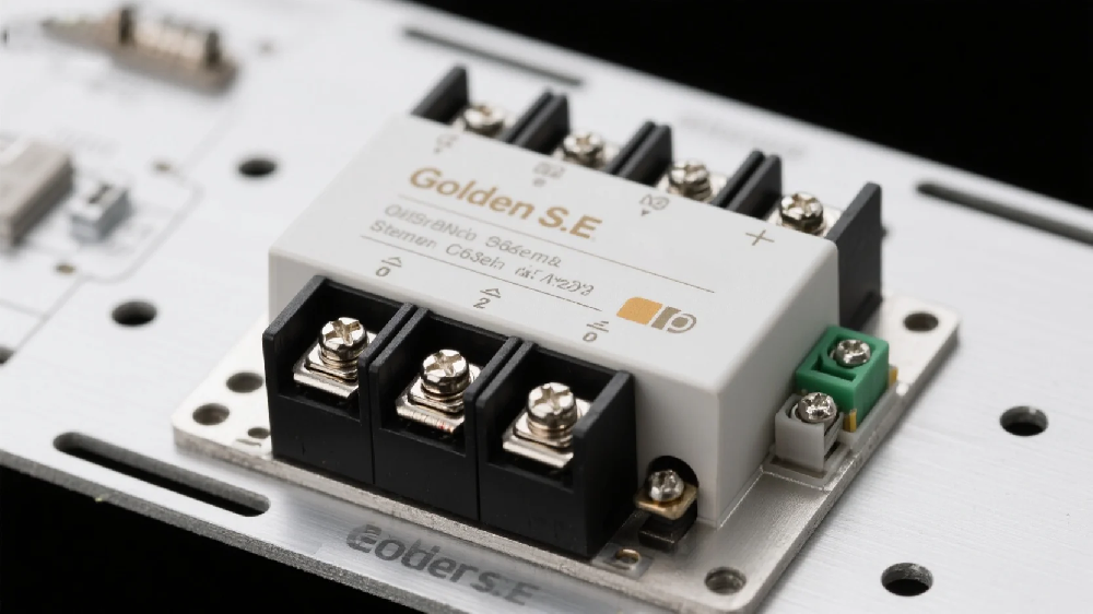
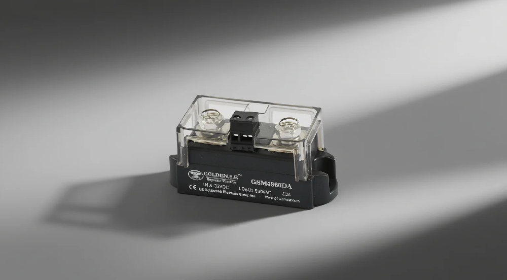
Solid-state relays are contactless electronic switches that use semiconductor devices (such as thyristors and transistors) to control circuit on and off. They achieve electrical isolation between input and output through optocoupling or transformer coupling. The internal structure of a solid-state relay can be divided into three major modules: input control circuit, isolation and drive circuit, and output power switch. Today, we will focus on the electronic components used in the isolation and drive circuit and output power switch.
Bidirectional Thyristor
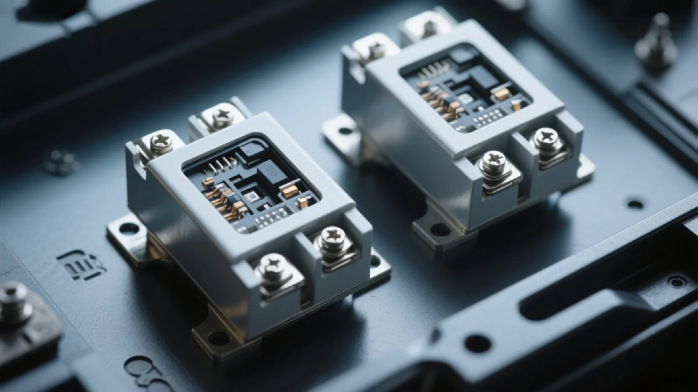 1. Bidirectional thyristor (TRIAC) is a three-terminal bidirectional AC switch device, belonging to a five-layer structure semiconductor device of NPNPN. It is developed based on the ordinary thyristor and can replace two ordinary thyristors connected in reverse parallel. It only requires one trigger circuit to achieve AC control. The three electrodes of the bidirectional thyristor are the main terminals T1, T2, and the control terminal G, and there is no distinction between anode and cathode.
2. Working Principle of Bidirectional Thyristor
The working principle of the bidirectional thyristor is based on the characteristics of PN junctions and specific trigger mechanisms, with the following key features:
2.1 Bidirectional Conduction Characteristics:
- Can achieve conduction and cutoff in both positive and negative directions;
- Equivalent to an integrated pair of ordinary thyristors connected in reverse parallel;
2.2 Trigger Mechanism:
- "One touch and go": When a trigger signal is applied to the control terminal G and there is a voltage between the main terminals, it conducts rapidly.
- "Self-locking maintenance": Once it conducts, it remains on even if the trigger signal disappears until the current drops below the holding value.
2.3 Structural Characteristics
- A power integrated device composed of seven transistors and multiple resistors;
- Small power products are packaged in plastic, while large power products are packaged in RD91 type;
3. Role of Bidirectional Thyristor in Solid-State Relays
3.1 AC Load Control
- Achieves contactless switch control of AC circuits;
- Replaces mechanical contacts, eliminating sparks and noise;
3.2 Signal Amplification and Isolation
- Weak current control of strong current through optocoupler isolation;
- Small input signals can directly drive large current loads;
3.3 Zero-crossing Control Function
- Cooperates with zero-crossing control circuits to switch states at the zero-crossing point of AC voltage;
- Reduces high-order harmonic interference and grid pollution;
3.4 Protection Function
- Cooperates with RC absorption circuits or varistors to suppress voltage spikes and surges; improves the reliability and lifespan of solid-state relays;
Due to its advantages of controlling high power with low power (amplification factor up to hundreds of thousands of times), microsecond response speed, and contactless operation, the bidirectional thyristor has become an ideal AC switch device in solid-state relays.
Definition of MOSFET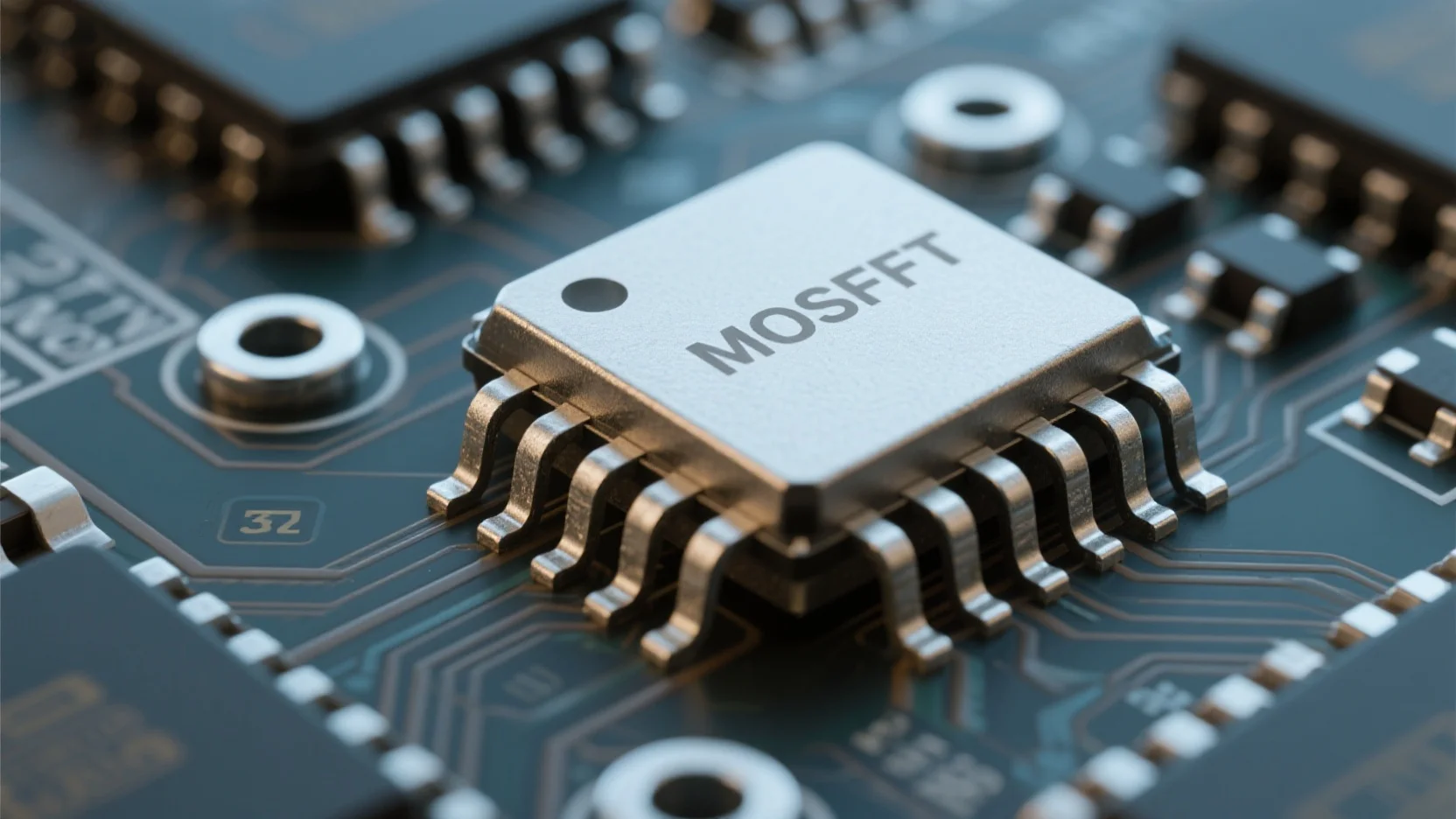
1. Definition of MOSFET
MOSFET (Metal-Oxide-Semiconductor Field-Effect Transistor) is a voltage-controlled semiconductor device that realizes switching functions by regulating the formation and disappearance of the conductive channel between the source and drain through the gate voltage. In solid-state relays, power MOSFETs are mainly used as core switch components.
2. Working Principle of MOSFET
2.1 Structural Characteristics:
- Composed of three terminals: gate (G), source (S), and drain (D);
- The gate and the channel are isolated by an oxide layer, forming an extremely high input impedance (10^9 to 10^12 Ω);
2.2 Conduction Mechanism:
- When the gate-source voltage (V_GS) exceeds the threshold voltage, a conductive channel is formed;
- N-channel enhancement type requires a positive voltage, while P-channel requires a negative voltage to trigger;
2.3 Bidirectional Conduction Characteristics:
- Special structure enables symmetrical conduction between the source and drain;
- Reverse current path is achieved through the body diode;
3. Role of MOSFET in SSR
3.1 Core Switch Function: Ø Replace mechanical contacts to achieve spark-free on-off;
Ø Typical switching speed reaches the microsecond level, over 1000 times faster than mechanical relays;
3.2 Photoelectric isolation drive:
Ø Combined with optocouplers to form a complete SSR module;
Ø The input side LED excites the photosensitive element to control the gate voltage;
3.3 Special application advantages:
Ø The preferred device for DC SSRs, with on-resistance as low as milliohms;
Ø Supports high-frequency switching (up to MHz);
3.4 Protection features:
Ø Built-in body diode can absorb the reverse electromotive force of inductive loads;
Ø Combined with heat dissipation design, it can carry tens of amperes of current;
MOSFET-type SSRs have become the preferred switching devices in industrial automation due to their contactless, long lifespan (up to 10^8 operations), and vibration resistance characteristics.
High-frequency transformer
1. Definition of high-frequency transformer
A high-frequency transformer is an electromagnetic energy conversion device that operates at frequencies significantly higher than the power frequency (50/60Hz), typically in the kHz to MHz range. In solid-state relays, it uses special core materials such as amorphous and nanocrystalline alloys to achieve electrical isolation and energy transmission through high-frequency electromagnetic induction.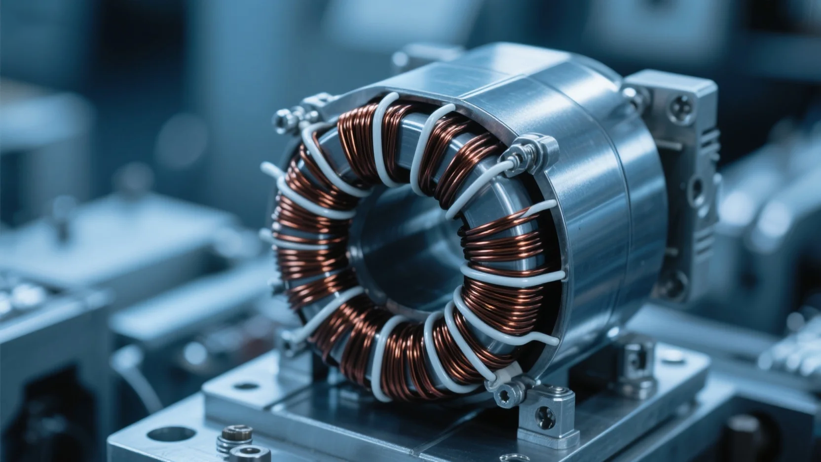
2. Working principle of high-frequency transformer
2.1 Electromagnetic induction mechanism:
Ø When high-frequency alternating current is applied to the primary coil, the core generates alternating magnetic flux;
Ø The secondary coil induces an electromotive force through magnetic coupling, achieving energy transfer;
2.2 Material property requirements:
Ø Utilizes low-loss iron-based amorphous/nanocrystalline alloy materials;
Ø Has high magnetic permeability and stable temperature characteristics;
2.3 Differences from traditional transformers:
Ø Operating frequency is increased by 100 to 1000 times;
Ø Volume is reduced to 1/5 to 1/10 of that of traditional transformers;
3. Role of high-frequency transformers in SSRs
3.1 Core isolation function:
Ø Achieves safe isolation between the control end and the load end (withstanding voltages up to 2.5-5kV);
Ø Replaces optocouplers through magnetic coupling, suitable for high-power applications;
3.2 Energy transmission characteristics:
Ø Transmission efficiency can reach 90-95%, far higher than the optocoupler solution;
Ø Supports bidirectional energy flow design;
3.3 Special application advantages:
Ø Enables high-frequency electrical energy conversion in solid-state transformers (SST);
Ø Combined with MOSFET/IGBT, it achieves nanosecond-level switching response;
3.4 System integration characteristics:
Ø Modular design can be integrated with heat dissipation structures;
Ø Supports multi-winding output for complex control logic;
The current amorphous and nanocrystalline core technology has broken through the capacity limitations of traditional high-frequency transformers, with single-module power reaching tens of kVA, providing key technical support for the development of SSRs towards higher power. This type of transformer can still operate stably at 200kHz, significantly enhancing the power density and reliability of solid-state relays.


