+1 227 241 2073

goldenssr@goldenssr.com

News News News News

News

Common installation methods for solid state relays

25-10-30

Common Installation Methods for Solid State Relays

There are three common installation methods for solid state relays: panel mounting, DIN rail mounting, and PCB mounting.

Panel Mounting:

481f4e3a55ba4e5783e091a328907564~tplv-tb4s082cfz-aigc_resize_mark_2400_2400.png

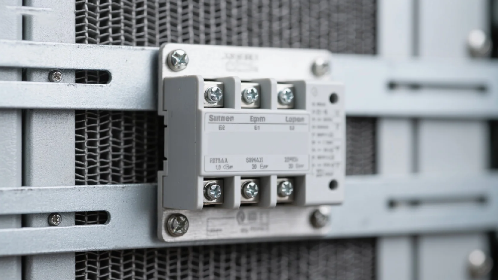
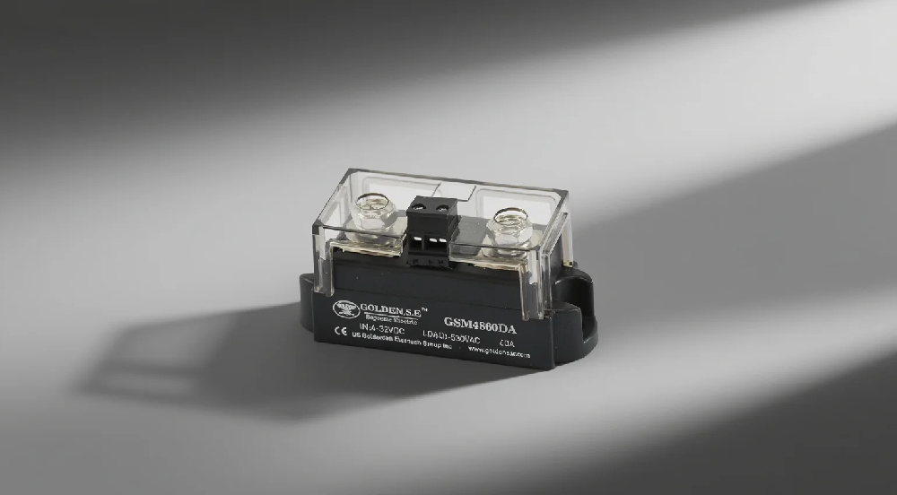
Panel mounting is the installation form where the solid state relay is fixed to the control cabinet panel or heat sink through mechanical means (such as screws). Its structural features include: using screw fixation (commonly M4/M5 bolts); the bottom is designed with a metal heat sink base (usually made of aluminum alloy), suitable for high current and high voltage (such as 480V AC) load scenarios (typical specifications 25-125A).

1. Core Advantages

1.1 Excellent Heat Dissipation Performance

Heat is directly conducted through the metal base, reducing thermal resistance by more than 40% compared to DIN rail mounting; it can be used with heat sinks to handle continuous currents above 50A.

1.2 High Mechanical Stability

Shock resistance up to 10G acceleration (military-grade standard); suitable for vibration environments (such as electric locomotives, mining equipment).

1.3 Installation Reliability

Screw fixation prevents accidental detachment; protection level can reach IP65 (dustproof and waterproof); suitable for harsh industrial environments such as high temperature, high humidity, and vibration.

2. Typical Application Scenarios

2.1 Industrial Automation Control

Motor control, solenoid valve drive; heating systems (such as electric furnaces, injection molding machine temperature control).

2.2 Power Distribution Systems

Smart meters, circuit breaker control; photovoltaic inverters, UPS power switching.

2.3 Special Industry Applications

Chemical explosion-proof environments; ships, railways, and other heavy equipment.

DIN Rail Mounting:

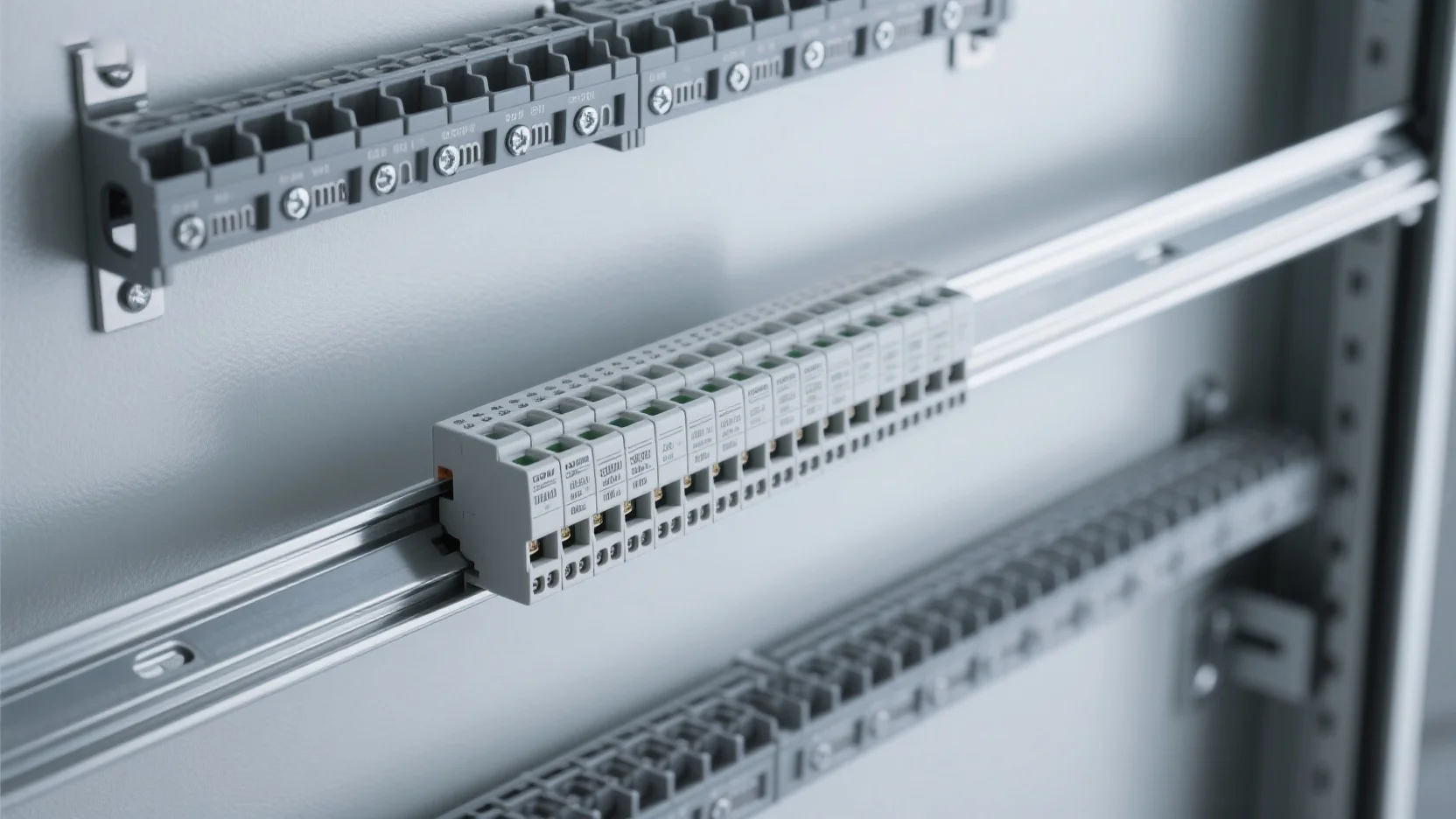
DIN rail mounting for solid state relays is specifically designed for industrial automation control cabinets, using a standardized installation form on standard DIN rails (35mm), which complies with the IEC 60715 TH35-7.5 rail standard; it uses a snap-on fixation structure, supporting tool-free installation and removal; multiple models can save 20% installation space.

1. Core Advantages

1.1 Quick Installation

Fixed without tools (snap-on installation), supports hot-swappable replacement, improving maintenance efficiency by more than 50%.

1.2 Optimized Space Utilization

Supports side-by-side installation of multiple modules; can be combined with PLCs, circuit breakers, and other devices to form modular control systems; the gap between adjacent modules only needs 10mm, saving 40% space compared to panel mounting; supports high-density arrangement.

1.3 Adaptability to Industrial Environments

Protection level reaches IP65 (dustproof and waterproof); shock resistance of 5-8G acceleration (meets industrial vibration standards).

2. Application Scenarios

626a4ceedc03458fa2ec1eabe82288dc~tplv-tb4s082cfz-aigc_resize_mark_2400_2400.png

2.1 Automated Production Lines

Motor start-stop control; conveyor belt speed control systems.

2.2 Energy Management

Photovoltaic inverter array switching; intelligent on-off control of distribution cabinets.

PCB Mounting:

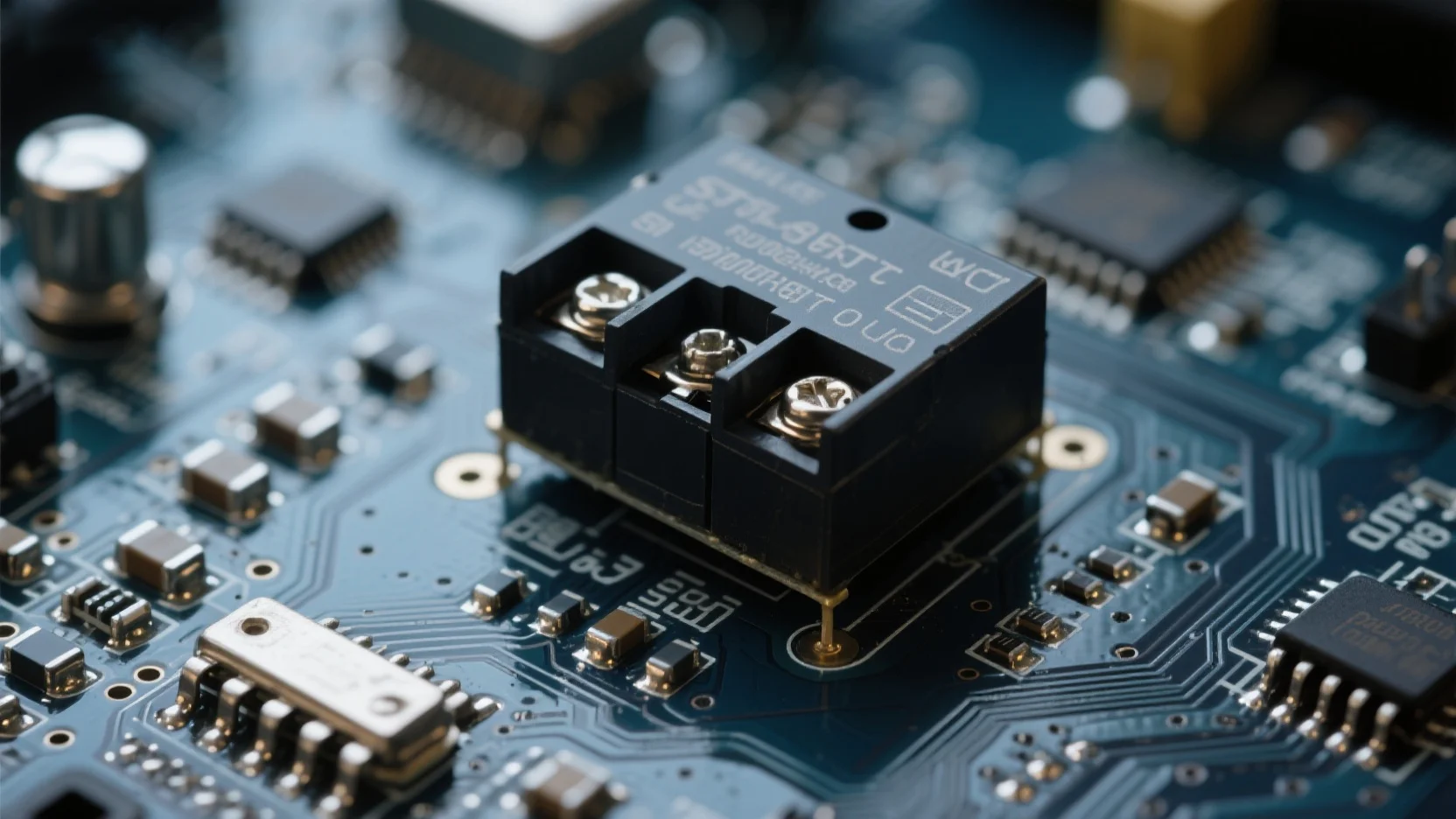
PCB-mounted solid state relays are integrated devices directly fixed on printed circuit boards through soldering, using SMD (surface mount) or THT (through-hole) packaging forms, with typical small-size designs, suitable for compact electronic devices with currents ≤10A.

1. Core Advantages

5b77ec0dc8cd44c9b1ac38551cb0cfb3~tplv-tb4s082cfz-aigc_resize_mark_2400_2400.png

1.1 Maximized Space Efficiency

Volume is reduced by more than 60% compared to DIN rail mounting, suitable for high-density circuit design; supports multi-layer PCB stacking installation, improving space utilization.

1.2 Compatibility with Production Automation

Adaptable to reflow soldering processes (peak temperature ≤260℃); placement machine placement speed can reach 50,000 points/hour.

1.3 Signal Integrity Optimization

Shortened circuit paths, reducing parasitic inductance and electromagnetic interference; more precise impedance matching (error ±5%).

2. Typical Application Scenarios

Consumer electronics (smart home control modules);

Medical electronic devices (portable testing instruments);

Automotive electronic systems (ECU control units);

Comparison of Three Installation Methods:

Parameter Panel-Mounted SSR PCB-Mounted SSR DIN Rail-Mounted SSR Installation method: Screw/clip fixation, Soldering (SMD/THT), DIN rail mounting

Rated current: 10A - 500A, 0.1A - 10A, 5A - 100A

Heat dissipation method: Metal housing + heat sink, Rely on PCB for heat dissipation, Some models come with heat sink base

Protection grade: IP65 (for some models), IP20 (no protection), IP20 - IP65

Applicable environment: Industrial grade (-40℃ - 80℃), Consumer electronics (0℃ - 60℃), Industrial grade (-25℃ - 60℃)


Contact Us

Customize your own solution

Contact Us