+1 227 241 2073
goldenssr@goldenssr.com
After understanding the outstanding performance of solid-state relays, a practical question arises: Faced with a wide variety of products on the market, how do you choose the most suitable one for your specific application? This is like finding the perfect key for a lock. Accurate selection is the prerequisite for fully leveraging the performance of solid-state relays and ensuring the stable operation of the system. Based on its rich industry experience, Godel Electric Group has sorted out the following key selection factors for you.
Step 1: Determine the load type and current - This is the foundation of selection
This is the most crucial step, directly determining the core parameters of the solid-state relay.
Load type: What device are you controlling?
Resistive load: such as heating tubes and incandescent lamps. The current is in phase with the voltage, and there is no inrush current during startup. The selection is the simplest.
Inductive loads: such as motors, transformers, and solenoid valves. At the moment of connection, they can generate surge currents up to 5 to 10 times the rated current. When disconnected, they will produce reverse high voltage due to self-induction. This is a key point that requires special attention during selection.
Capacitive load: such as switching power supplies, LED drivers. At the moment of connection, it is equivalent to a short circuit and will generate a huge inrush current.
Current calculation: It is essential to select the output current of the solid-state relay based on the rated operating current of the load. For inductive and capacitive loads, a sufficient margin must be left to handle surge currents. A general rule of thumb is to choose a solid-state relay with a rated current that is 2 to 4 times or more of the load's steady-state current. For instance, for a motor with a steady-state current of 5A, it is recommended to use a solid-state relay with at least 10A, or even 15A or 20A.
Step 2: Determine the voltage and power supply type - AC or DC?
Solid state relays are "exclusive". The internal structure and principle of AC output type and DC output type are completely different. They must never be used interchangeably!
Control AC load: Select AC output solid-state relays. Pay attention to two voltage parameters: one is the load power supply voltage (such as 220VAC or 380VAC), and the other is the rated output voltage of the solid-state relay. Make sure the latter is greater than the former.
Control of DC loads: Select DC output solid-state relays. It is also necessary to confirm that the load voltage is within the rated output voltage range of the solid-state relay.
Step 3: Examine the control signal - Ensure accurate instructions
What kind of signal is being sent by your PLC, microcontroller, or sensor? This determines the input specifications of the solid-state relay.
Control voltage range: Common input control voltages include 3-32VDC (wide voltage DC), 4-20mA (current loop, strong anti-interference), 90-280VAC (AC control), etc. Ensure that the signal output by your control device perfectly matches the input requirements of the solid state relay.
Input current: Understand the minimum current required to drive a solid-state relay to ensure that your control port can provide sufficient driving capability.
Step Four: Consider Installation and Environment - Ensuring Long-Term Operation and Smooth Sailing
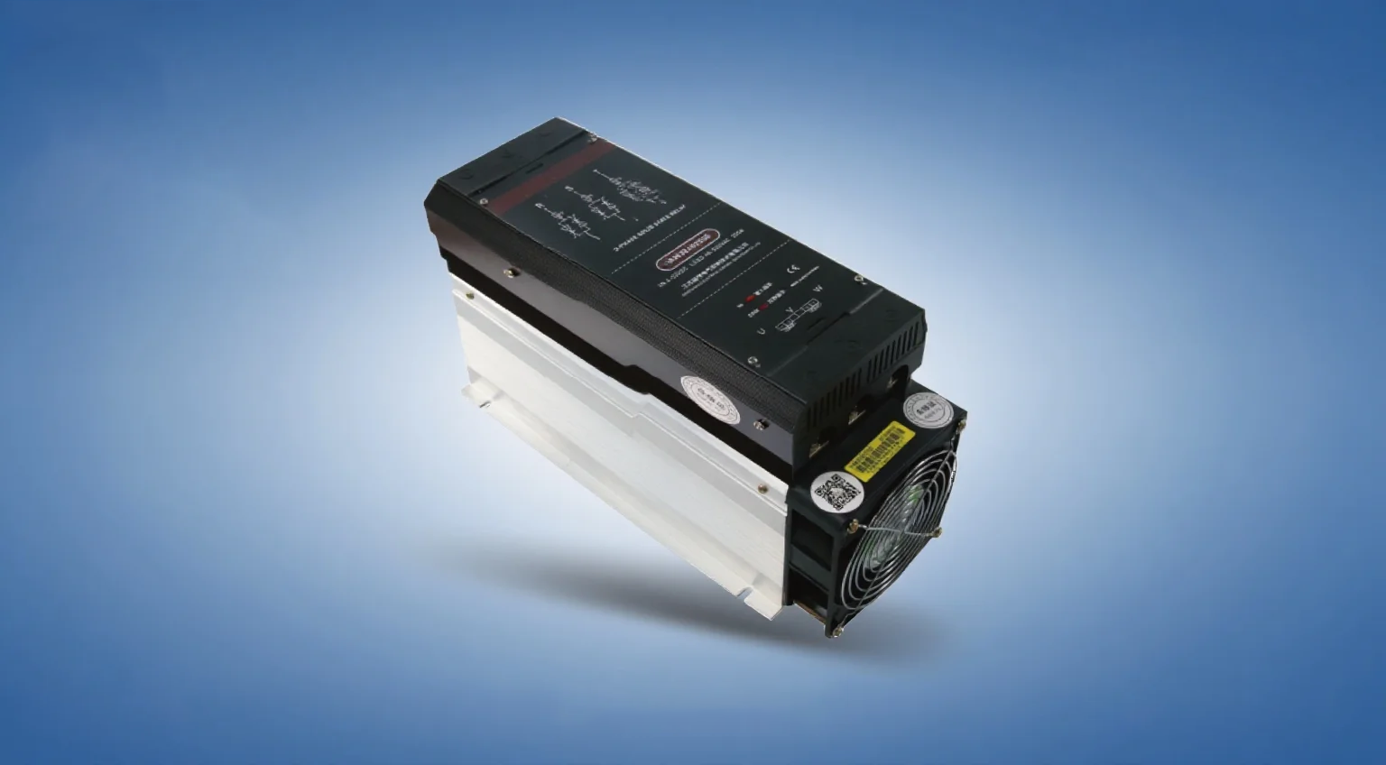
Heat dissipation design: Semiconductors generate heat when conducting. When the current is large (usually > 5A), a heat sink must be installed! Ignoring heat dissipation is the main cause of early failure of solid-state relays. The heat dissipation power needs to be calculated based on the actual current, and the appropriate size of the heat sink should be selected. In some cases, even forced air cooling is necessary.
Installation methods: Common ones include multi-functional DIN rail mounting and screw mounting. Please choose according to your electrical cabinet design.
Ambient temperature: The current-carrying capacity of solid-state relays decreases as the ambient temperature rises. In high-temperature environments, derating is necessary, meaning that products with a higher rated current should be selected.
Step 5: Focus on Protection and Additional Features - Enhance System Security
Built-in protection: Many solid-state relays incorporate RC snubber circuits or varistors internally to suppress voltage spikes during turn-off, which is crucial for protecting inductive loads. Verify whether the product has these features.
Status indication: Solid-state relays with LED indicator lights can visually display their working status, greatly facilitating on-site debugging and fault diagnosis.
Zero-crossing trigger type and random start type (AC output only):
Zero-crossing trigger type: It conducts near the zero-crossing point of the AC voltage, effectively suppressing radio frequency interference and reducing the impact on the power grid. It is the preferred choice for controlling inductive and capacitive loads.
Random opening type: It conducts immediately upon receiving the signal, suitable for controlling resistive loads that require rapid response.
Gordon Electric's Suggestion
Selection is a systematic project that requires comprehensive consideration. The technical team of Gordon Electric Group is always committed to providing professional selection support to customers. We suggest that when making a choice, you should not only focus on the initial cost but also take into account the total cost of ownership throughout the entire life cycle. A correctly selected and reliably operating solid-state relay will bring about a significant improvement in system stability and a reduction in maintenance costs, far exceeding its own value. In the next article, we will share the best practices and common misunderstandings in the installation and use of solid-state relays.